This is a simple digital counter with a serial rs-232 and a 7 segment display, i started this project to count items on some shelfs, but it can be used for anything, it is also, for the exception of the connectors, completely on SMD components.
The circuit is made around a PIC16F88, and takes use of its internall EEPROM to store the number.
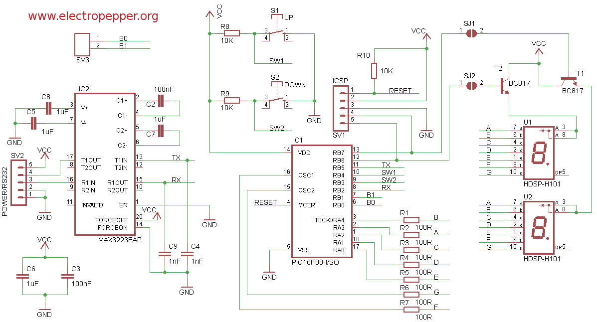
Im using PORTA to connect directly to the segment display thru a 100R resistor in each segment to protect each segment of the displays, then i use two lines from PORTB to multiplex the displays into showing units and decimals, by using the timer2 overflow interrupt with the presler at 1 meaning, if im not rong, that the display refresh at 250 nanoseconds thus impossible for the human eye to see. Each of this two lines connect first to the base of a transistor that drives the common anode on the 7 segment display, this way i spare my chip from suplying the main current thru it,prevents overheating and its always good practice to get power from the source.
Also on PORTB there are two lines from the switches, both switches have a pull-up resistor so when the button is pressed they go to ground, so the PIC is reading a 0 if the button is pressed.
I puted also a standard ICSP connector SV1, you can actually use this configuration of the ICSP connector to almost any microchip microcontroller, at least until today i havent found one that it didnt work.
The second chip on the schematic is a standard rs-232 level converter, ive wired it as in the datasheet and connected on the PIC AUSART(Addressable Universal Synchronous Asynchronous Receiver Transmitter) module, its the only part of the circuit not tested yet, i havent made any code to work with it.
The entire circuit is powered directly with 5V from the connector wich includes also the serial TX and RX lines to connect to a PC, i can later also see the numbers on the computer and even insert numbers into it, also ill write software to read several counters and colect the data into a computer to monitor shelfs items and manage stock.
And finally i have a two pins small header with the last remaining unconected pins, i usually do this so i can access them in the future if necessary, for example to add more functions to the circuit.
Here is the circuit that i a made with eagle :
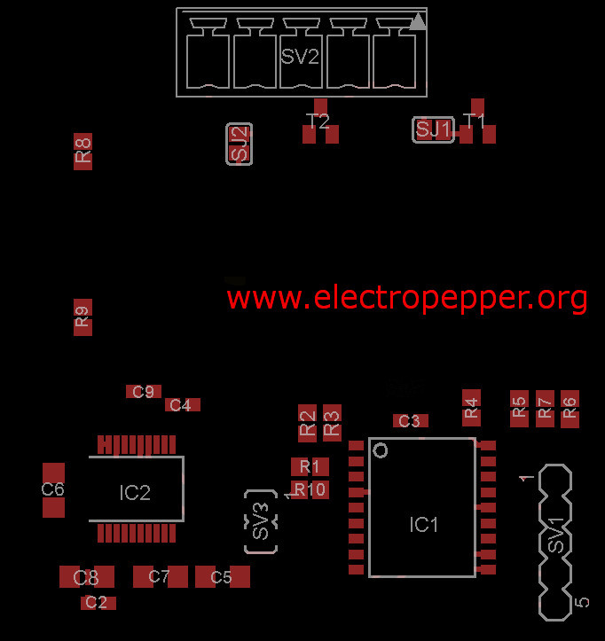
Placing and part list :
BOM (Bill of Materials)
| Reference | Value | Package |
|---|---|---|
| R1–R7 | 100 Ω | R0805 |
| R8-R10 | 10 kΩ | R0805 |
| C2, C3 | 100 nF | C0603 |
| C4, C9 | 1 nF | C0603 |
| C5-C8 | 1 uF | C1206 |
| IC1 | PIC16F88 | SO-18 |
| IC2 | MAX3223EAP | SSOP20 |
| S1 | Push button | B3F-4000 |
| S2 | Push button | B3F-4000 |
| SV1 | PIN HEADER-5 PINS | |
| SV3 | PIN HEADER-2 PINS | |
| SV2 | MA05-3.81-5 | |
| T1, T2 | BC817 | SOT23 |
| U1, U2 | 7Segment Display | HDSP-H101 |
Most of this components i got from farnell
But if you really want to build this and run into problems, you can always contact me
, i still have some spare parts.
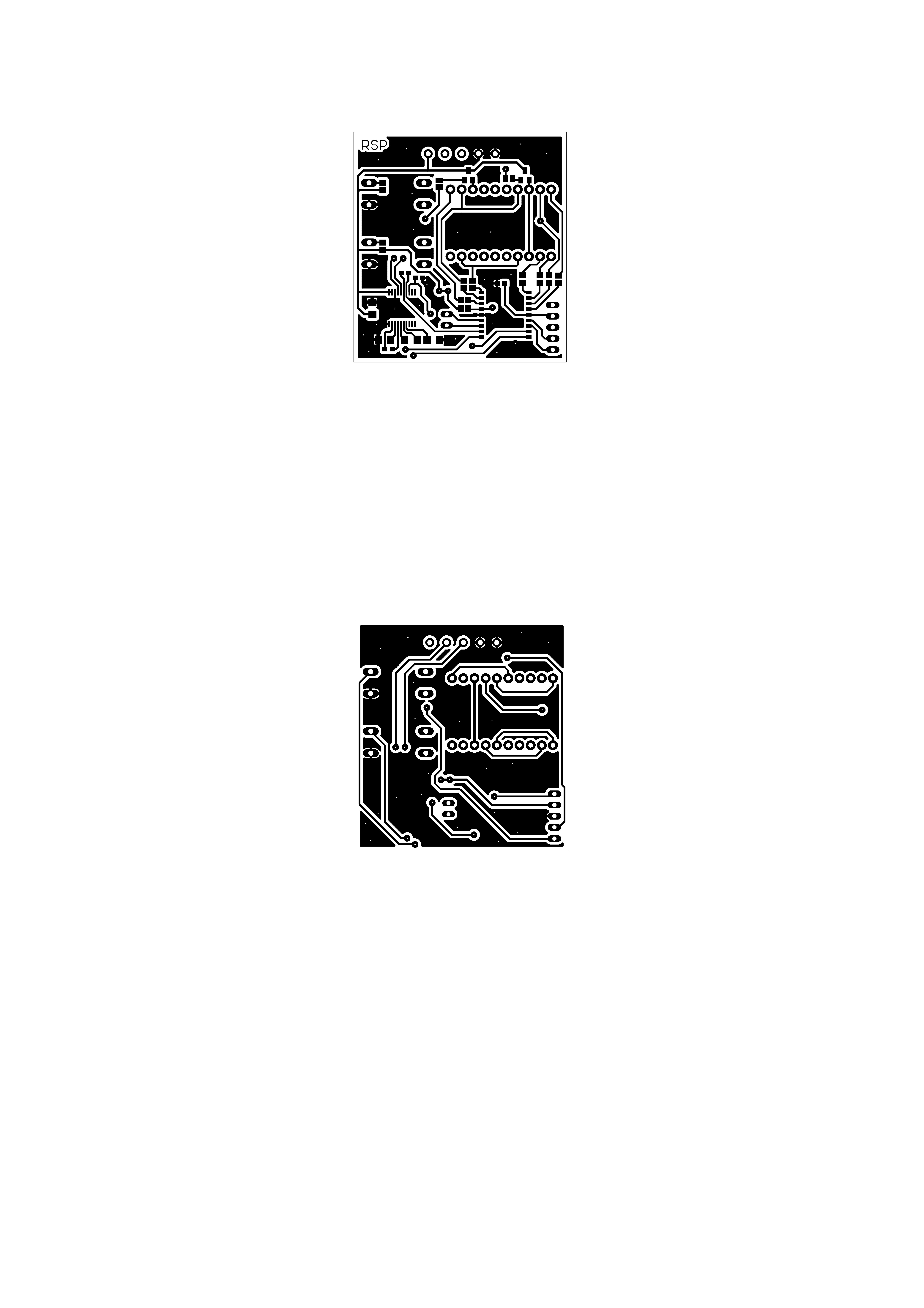
Here goes the top and bottom, right click and, save image as, then you can print this to make your board.
have made the source code in assembly using the microchip MPLABX , its a really good IDE, as ive mentioned i havent written code for the serial comunication yet, im planning to that further ahead in C language, while assembly is a really good language to learn how things work on a hardware level, it just takes to much time to develop something, later on i will put here the rest, meaning that the firmware for the pic V1.0 hasnt got the max3223 working, so if you wish to build this you can skeep this chip for this version.
Then the firmware in Assembly, C and the HEX file ready to load up with a programmer.
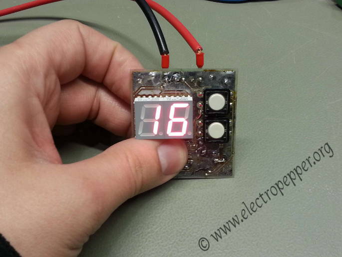
This is the final look of the counter :
Here are some small videos :
Created on 22-12-2012