Proto I/Os Rev. A
Another board with several I/Os, like the Proto I/Os arduino this board was designed to save you time on prototyping or learning new development boards by quickly adding extra LED's, buttons a buzzer and a temperature sensor.
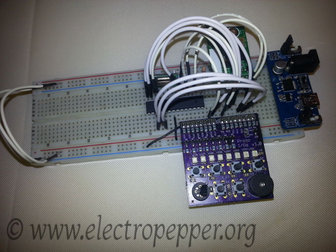
The main objective of this board is to spare you time and bad connections while prototyping learning and/or developing electronics, by adding to development boards like Raspberry Pi, Arduino, etc. The main headers on the board can be fit with male or female headers. With the female header the board can be used just about with any development board or microcontroller with wires but the main particularity of this board, when assembled with male headers is that it has two power pins(JP3->Vcc, JP4->GND) that align exactly with the power rail on a breadboard and the rest of the pins align with the breadboard aswell for a perfect plug'n'play fit, has you can see on the picture below.
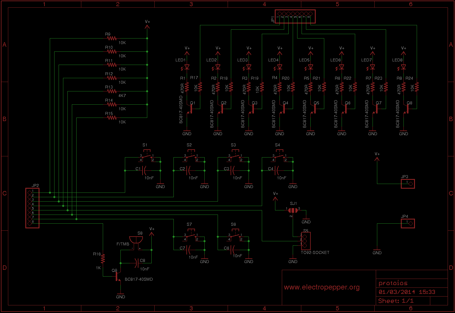
The circuit is very simple, starting with the LED's:
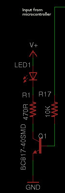
They all have a small transistor has a driver, so the voltage output from your microcontroller or other device can also be diferent from the LED power supply, this can be advantageous at some times.
Next the buttons:
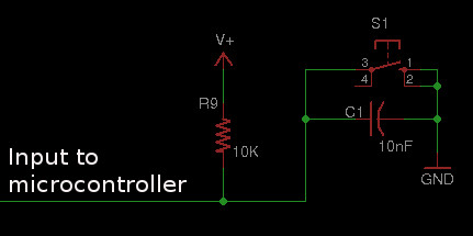
Every button has a pull-up resistor and a small debounce capacitor, so when the button is pressed the line goes to GND or low, meaning is ACTIVE LOW.
The buzzer:
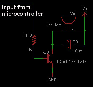
The buzzer can be supplied with voltage up to 6V and has again a transistor to drive it.
The one wire protocol device:
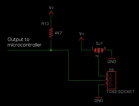
In this case i have a DS1820 temperature sensor, but there are other one wire protocol devices like eeprom for example. I have a jumper to chose if the device works in parasite mode or not, read more about ir here.
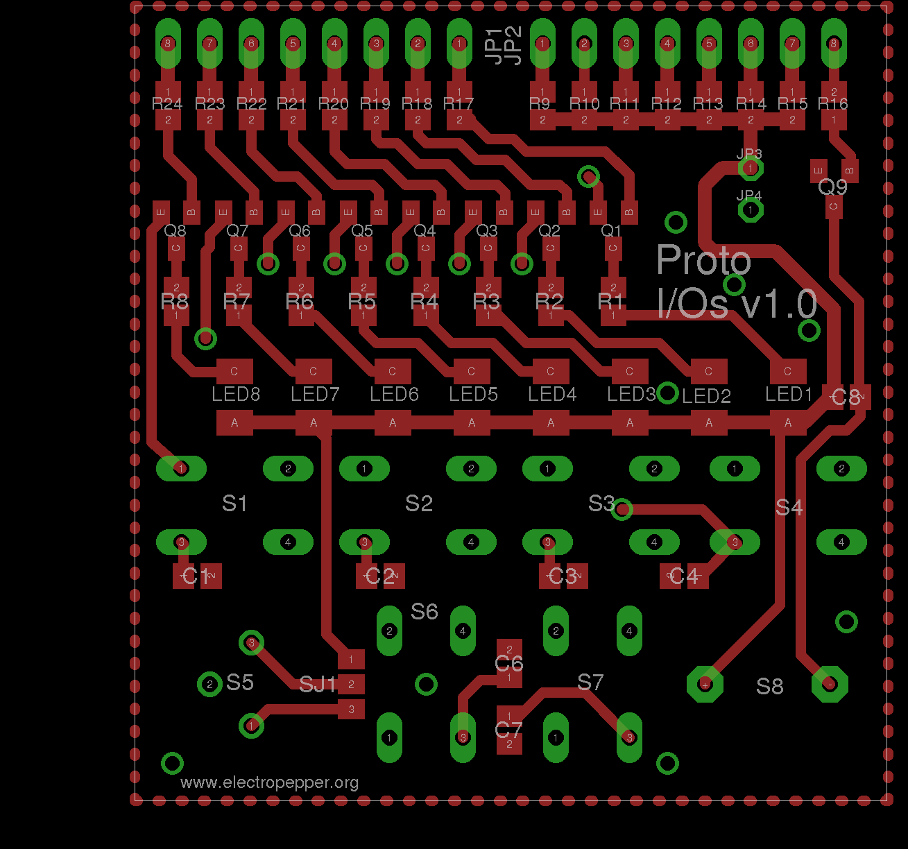
Placing and parts list:
BOM (Bill of Materials)
| Reference | Value | Package |
|---|---|---|
| R1–R8 | 470 Ω | R0805 |
| R16 | 1 kΩ | R0805 |
| R13 | 4k7 Ω | R0805 |
| R9-R12, R14, R15, R17-R24 | 10k Ω | R0805 |
| C1–C4, C6-C8 | 10 nF | C0805 |
| Q1-Q9 | BC817 | SOT-23 |
| LED1–LED8 | LED | KA-3528ASYC |
| S1–S4, S6, S7 | Button | B3F-10XX |
| S5 | DS18S20 | 3-pin socket |
| S8 | Buzzer | - |
Most of the components can be found in farnell, But if you really want to build this and run into problems, you can always contact me, i still have a lot of spare parts.
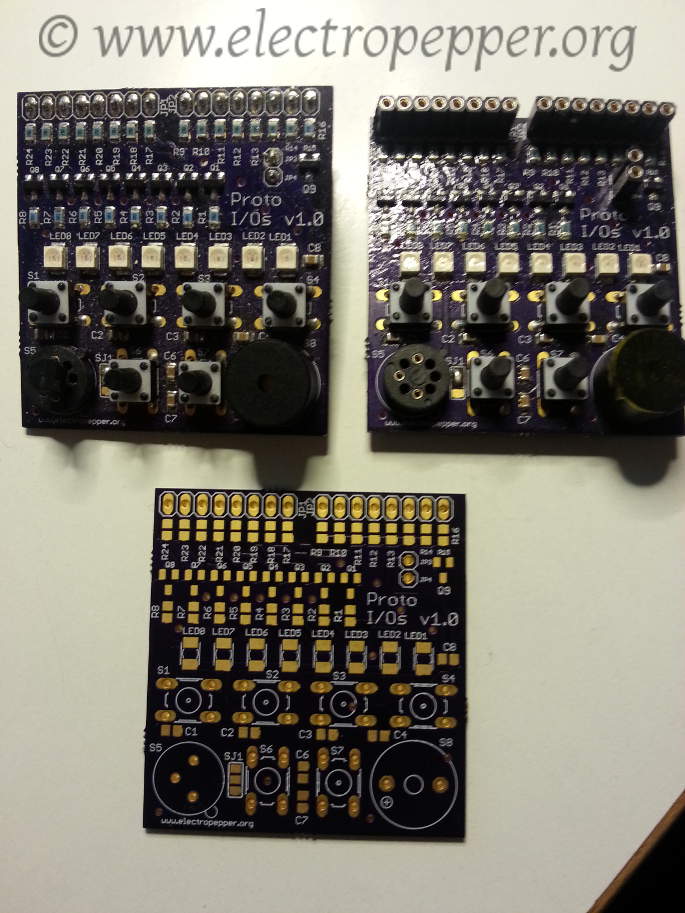
I have made the PCB with the Osh park service, here is the clean and built PCBs :
The PCB is also available to be ordered from here Osh park shared project.
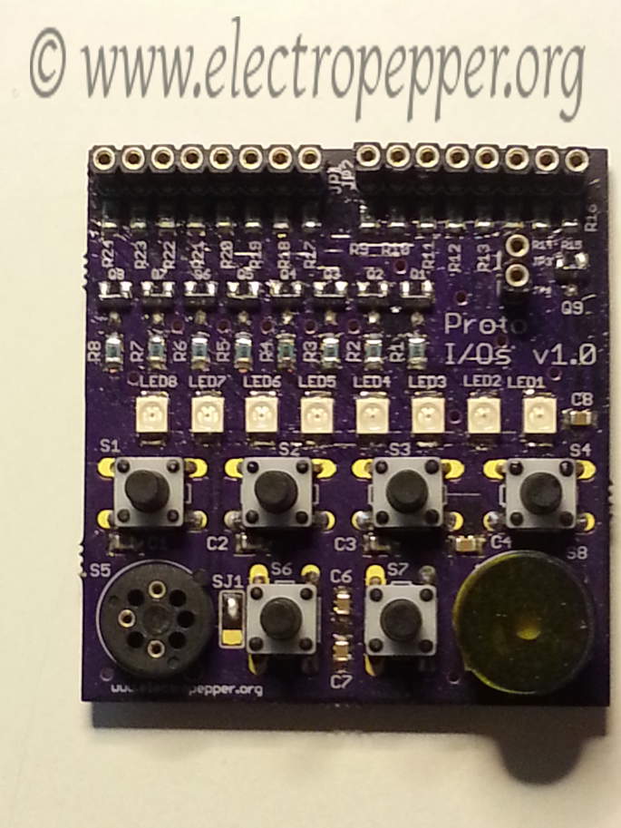
A picture of the board fully assembled:
Below is a video of the test:
Created on 20-04-2014